The Importance of Preventive Maintenance in Conveyor Pulleys

Keep conveyor belts moving by implementing a coordinated approach to system support, a mechanical upkeep strategy that extends the lifespan of your conveyor pulleys. Competent working practices take the form of a first-class preventative maintenance strategy, a standard means of periodically checking system components during a normal operational state, so as to instigate a powerful facilities management policy. On taking the assessment procedures and repairs to the next level, the work goes beyond surface evaluations, beyond peering into the surface of the belt, and descends to the inner workings, thus expertly monitoring the condition of pulleys, motors, and all essential parts of the drive system.

Penalizing Productivity

A poorly maintained conveyor belt threatens productivity, stopping the manufacturing cycle from moving between assembling stations and production machinery. In fact, the whole facility will come to a grinding halt if the conveyor gear decides to pack up and stop. A properly organized preventative maintenance plan spots minor issues and repairs these trivial problems before they can worsen and turn into major breakdowns. The periodic nature of the process documents these problems, tracking the condition of the machinery for troubling signs of system deterioration. Of particular interest in this scenario is the conveyor pulleys, core parts that bridge the drive system and the belt. A poorly maintained pulley will lose its smooth rolling characteristics due to a lack of lubrication on the bearings. The pulleys are critical production links in a chain of product carriage that must be supported over a 24/7 run period, meaning any downtime whatsoever will incur costly losses.

Intolerable Downtime Avoidance

Tension is the next key property, one that keeps company with bearing integrity. The many disparate load factors that have an untoward effect on load pulleys include torsional and shearing events, forces that work at an angle to the axis of the pulley shaft. Irregular operation begins to introduce eccentric rubbing action into the system, movement that wears drum cladding and dramatically lowers the operational efficiency of the belt. The conveyor pulleys suffer from stress, a mechanical pressure that alters the tension of the conveyor belt. A conscientiously observed preventative maintenance program takes note of tension changes over time and corrects the problem if system tolerances are compromised. This corrective action restores tension, thus preserving the rigidity factor of the belt across all pulleys. The result of the preventative strategy is improved productivity, the elimination of costly downtime, and a custodial preservation of both bearing integrity and belt tension.

The goal of preventative maintenance is to predict a weak link in the production chain and to repair that link before it turns into a time-consuming and profit-eating breakdown.

The Importance of Engineering and Dimensions in Conveyor Pulleys

drawingA smoothly operating conveyor system is a thing of engineered beauty. Take away this fluid movement and you risk ending this harmonious arrangement. The chain of energy transmission becomes unstable. Uneven wear patterns develop. The conveyor pulleys suffer. Performance is compromised, and this distressing scene undermines the reliability of the equipment. Balance is lost, to be sure, but this is no abstract notion. The lost balance referenced in this case touches upon energy losses and stunted operation cycles. The machinery is subject to greater breakdown incidents, and the period between maintenance inspections shrinks, resulting in greater down time and lost productivity.

Incorporating Parallelism and a Concentric Operational Profile

In order to match radial movement across all conveyor pulleys, the components are manufactured to exacting dimensional standards. The rollers and shafts, housings and drums may look huge, but scale is no excuse for shoddy geometrical exactitude. The shafts are therefore aligned properly to avoid shearing effects, a phenomenon that’s not always observable over the course of a few days or weeks, but it’s one that will eventually be picked up and documented by the maintenance team when expensive abrasive affects pop up along the belt. Next, the drum and shaft represent the second axis under consideration. The 90 degree twist in thinking takes our perspective across to the drums and the lagged surfaces, for it’s at this point that full mechanical contact takes place between the belt and the drum. It’s therefore essential that the parts are level and free of the peaks and troughs that would otherwise transform a formerly level belt into a rippling mess.

Bearing and Housing Misalignments

High-end conveyor systems depend on the belt and drum arrangement, on conveyor pulleys that deliver when it comes to pure engineering characteristics, but it’s down into the smaller realms, into the bearings and housings that support those bearings that trouble often takes root. If even one end of the pulley is fractionally out of alignment, skewed to one side or another, then the twin races of the bearings are bound to be subjected to off balance forces. The small balls face additional stress, and this mechanical pressure will offset the superior friction-cancelling attributes of even the best bearing.

Engineering exactitude and dimensional uniformity may not seem important when talking of larger-than-life equipment, but even a single degree of misalignment can spell disaster over time. The equipment is straining to work efficiently but is doing so while off balance. Thankfully, there are tests to evaluate the uniformity of the system, and some adjustments are made possible by opening the bearing housings. Meanwhile, as far as dimensions go, the best answer is to choose a manufacturer who has a reputation for building high-quality system components, parts that are quality assured to meet refined system specifications.

What is Lagging in Conveyor Pulleys and How Does It Work?

If you’re a heating engineer, then lagging is the insulating material that covers pipes and boilers. Alternatively, if you’re an engineer with pulley know-how and conveyor expertise, then the term describes a completely different component asset. It’s funny how a simple switch of professions can so alter the context of a single word. Anyway, when conveyor pulleys are lagged, they’re still being coated, but this coating is designed as a dynamic material, one that deals with the contact areas between the conveyor belt and the drum of the pulley.

Describing Pulley to Belt Energy Translation

The pulleys and motor-driven shafts of a conveyor system can be compared to the muscles and joints of a human body, though movement is restricted to a linear progression as directed by the radial turn of a series of horizontally-mounted rollers and pulleys. Some of these components are simple passive rollers, parts that add tension and direction to the system, but other pulleys incorporate drive mechanics. Regardless of this layout, the belt has to contact the pulleys as they turn. Note, the belt is technically rubbing against the rolled drum and not the shaft. This is a fine distinction but an important one when explaining lagging, because this drum is clothed in a blanket, one that exhibits essential grip characteristics, which is why the material is often fabricated from a tough rubber.

Drum Mechanics VS. Belt Friction

The friction coefficient between a belt, an endless loop of stout rubber, and the rolling conveyor pulleys can represent a substantial energy loss point unless a traction mechanism is incorporated between these two disparate assemblies. Imagine using a pulley system without a blanketing rubber coating. The pulley would rotate as designed, but there would be no traction between the underside of the belt and the exterior of the pulley drum. The lagging solution ensures the contact point between both the drum and the belt fully meshes. Full energy transmission can now take place across the system.

Conveyor Pulleys Need Tough Blankets

The lagged blanket doesn’t keep the pulley warm, but it does deliver mechanical efficiency. As such, the rubber blanketing has to be fabricated to the same standards as the belt material. The drum coating will therefore resist the abrasion effects generated by possible friction events, will maintain contact as guided by the tensioning subsystem, and must do all of this while delivering a low maintenance profile. Additionally, when maintenance issues do occur, it’s far more cost-effective to replace a slightly worn rubber coating rather than an expensive drive pulley.

A number of variants exist within the drum coating industry, replaceable coatings that are often compared to car tyres. They sport diamond-grip patterns, added channels for distributing friction, and a number of other optional extras.

What Is An Idler Pulley?

idlerAn idler pulley is as important as any other component, in the grand order of things. It doesn’t generate energy or rotate parts, so it perhaps doesn’t belong in the same family as drive pulleys, but the part still possesses a pivotal role. Engine idlers, for example, are characterized by their dual functions. The pulley regulates the belt, especially when the belt takes on a complex geometrical outline. Serpentine belts assume this role, taking convoluted paths when driving a series of drive assemblies. The idler is essential here because it’s acting as both a guide and a much needed system tension handler.

An Idler Pulley Delivers Adjustable Tension

Far from only being a sidelined member of the pulley family, the idler is an active component. Without it the belt is slack and mechanical parts lose their snappy momentum. System efficiency is lost. As a matter of fact, some large pulley assemblies absolutely depend on idler mechanics so much that added features have gone into their design. The supplemental elements include hydraulic or spring-loaded gears and other innovative mechanical solutions. Of course, moving parts lose positional sureness over time as soft metals bend and loosened parts rub against each other, which means an adjusting mechanism has to be part of the component’s anatomy. If a conveyor system is failing, making noises and drifting into breakdown territory, then an engineer’s first stop may indeed be the idler assembly.

Applications for Idler Pulley Units

It doesn’t matter whether we class the part as a belt guider or a tension maximizing implement, its role as a system regulator is very much established. A car mechanic works dutifully on his idler adjusting duties while attempting to regulate a recalcitrant vehicle engine. An idler works in concert with a mechanical governor when a large-scale electrical generator is transmitting electricity from a mechanical turbine. One or more units safeguard industrial conveyor systems in a working mine or a dust-filled quarry, keeping a round, rotating metaphorical finger on the pulse of the belt drive.

On returning to a specific application, the conveyor industry, the regulating properties of the idler ensure the belt of the conveyor continues moving smoothly and reliably. This promise of consistency is held in place by mechanisms that are built from durable materials and exhaustingly engineered components. The drive system is arguably the most important part of the conveyor, but a belt that doesn’t move in a consistently linear fashion would be a poor example of the process. The idler thus governs movement, compensating through hydraulic energy or spring motion to compensate for load-introduced irregularities, such as the transient rocky loads we often see trundling along mining conveyors as ore-rich chunks of geological matter shift and get dumped onto the belt.

The Significance of Bearing Housings in Conveyor Pulleys

housingSpeed and load calculations define the theoretical limits of conveyor systems. Rollers use these figures, converting radial motion into belt-driven linear momentum. In an ideal world this efficient transfer of energy would drive pulleys, the roller would push the conveyor belt, and the system would mesh to effortlessly deliver heavy loads. Of course, conditions are rarely if ever ideal. The mining industry, for example, fills the air with dust. Quarrying operations face the same issues, although its fine clouds of coarse granite that coat surfaces in this instance. Layers of toughened materials, cladding and premium metal alloys, battle the bulk of these machine-degrading elements, which leaves bearing housings in conveyor pulleys the role of ejecting contaminants before they can reach the moving heart of the mechanism.

Bearing Housings in Conveyor Pulleys Support Energy Transmission

Bearing housings are engineered to contain a variety of differing innards, workings that drive pulleys smoothly. They’re forged from metal and built to cradle fine bearings. The housing contains friction-eliminating components, stationary circular rails and fast-moving rings that are keyed to the shafts of system-essential pulleys. Lubrication is a primary concern in this environment, as is the conduction of latent heat away from the hot bearings. It’s inside this casing, after all, that dynamic motion and the anchoring of stationary components combine precisely like a lock and key, although, at least in this specialist case, the key is a rotating shaft. The housing channels lubrication to the bearing and balances this act by moving heat away from the moving parts.

Bearing Housings are Key in Sealing Virgin Territory

Machine housings are notable for their adjustable builds, for being able to compensate for the day-to-day influences of rocky matter moving at speed. As compelling a feature as a calibration mechanism is, we’re still missing the biggest talent of the enclosure. Bearing enclosures are indeed designed to aid in heat reduction and keep a lubricant just where it’s required, but the primary skill of the enclosure comes from its contaminant shielding aptitude. Remember, this isn’t an ideal application for a shaft and its associated bearings. The ideal situation would be a dust-free environment and a zero-friction lubricant that possesses pure chemical compounds. Unfortunately, this is a dirty mine, a gritty quarry, or even a carbon-choked power station. The housing has to fit a profile that matches a moving shaft but still seal the innards from the dusty matter bumping along the conveyor belt.

Auxiliary mechanisms are often built into bearing housings, and these supplemental parts are designed to use centrifugal force to “spin out” moisture and dust, but the best resolution here is still to employ a seal, one that favours maintenance but is pure-bred to provide an inviolable physical barrier.

Applications of Shaft Locks in Conveyor Pulleys

shaft-lockConveyor pulleys transmit motorized power into long belts, acting as the origin of the workhorse momentum that drives the system. The dynamic force encountered on the belt and is challenging at the best of times, but starting inertia is slowly overcome until the equipment is spinning merrily. It’s the duty of shaft locks to ground this rotating motion, to host friction-cancelling bearings, keyed and keyless shafts, and bridge the radial force spinning the conveyor pulleys so that the system is securely anchored to a stationary seat.

Cataloguing Shaft Lock Applications

Alignment is one of the pet peeves of setting up a conveyor system. Shaft locking mechanisms accommodate axial movement adjustments across a bank of conveyor pulleys, thus ensuring the belt is free of lateral movement issues. This kind of scenario is commonly experienced when transient loads become a problem. Conveyor systems that handle large loads and intermittent shocks require a reliable locking solution that can also adjust when alignment becomes problematic, thus illustrating one of the higher level roles of these anchoring assemblies. Yes, shaft locks are accessible for maintenance, for lubrication and alignment adjustments, but this fluid versatility factor must never undermine the steadfast reliability of the components.

The above mandate applies to mining conveyors and quarries, but it also has relevance in small package scenarios. The transferral of pharmaceutical commodities and mail packages are one example of this utilization archetype, with the shaft locks focusing less on loading capabilities and more on a bias for relative orientation vis-a-vis the goods located in a grid pattern on the conveyor.

Stresses encountered within a typical conveyor system:

  • Slippage
  • Alignment issues
  • Shaft play
  • Back lash

The Shaft and Lock Production Environment

Manufacturers offset the dynamic forces running between the shaft-to-seat assembly of today’s shaft locking products by adopting a state-of-the-art approach to the engineering obstacles that regulate modern conveyor science. Locking components can be either keyed or keyless, equipped with a splined shaft or threads and grooves, as long as the product is studiously analysed so that an application study accounts for the eccentricities introduced by any particular configuration. This includes tension forces, side-added axial movement, and other unpredictably energetic phenomena. When planning for this messy clash of radial and axial momentum, centrifugal and lateral force, only the very best locks will do for the most geometrically shaped pulleys.

The Importance of Timing and Accuracy in Conveyor Pulleys

pulleyAn industrial conveyor system such as that used in mines and quarries, move quarried rocks and mined aggregate along conveyor belts supported on rollers from the seam to the surface. Conveyor pulleys and high-HP motors are positioned along the belt to move the material to the surface. Load chutes and discharge buckets at either end of the belt keep the process moving.

Pulleys are generally classified as single-fixed, movable, or compound pulleys. Single-fixed pulleys are simple and only require equal amounts of load to force to lift the load. They allow the load to shift stress-free, although the force must change direction to complete a task.

The movable pulley’s wheel moves with the load as the load moves. It increases the applied force which ultimately makes it easier to move the load. Movable pulleys must be pulled or pushed, however, to displace the load.

Compound pulleys are a combination of movable and single-fixed pulleys which form a block and tackle.

Maintaining Timing and Accuracy

The conveyor system is integral to production. Monitoring and maintaining pulley bearings, housings, seals, and central- and single-point lubrication parts and elements maintain and increase “uptime,” efficient operation, and production, particularly for conveyor pulleys operating in port, mine, and power plant environments and conditions.

Engineered pulleys are designed to meet specific project requirements. Effective conveyor pulleys and system depend upon:

• a complete design analysis,
• high-quality materials and components,
• specifically-designed tolerances,
• accurately-measured shaft and roller diameters,
• specifically-designed shaft (infinite) fatigue life, and
• stress resistant welded connections.

Concentric design addresses stress loading tolerances and fatigue which contribute to the overall timing and accuracy of the conveyor pulley assembly. Shaft bending and deflection and shear stresses are designed for the conveyor pulley disc. It is critical the shaft’s diameter is sufficiently wide enough to offset stresses on it. Alloy material selection significantly reduces negative rotation caused by stress that might interrupt the smooth conveyor motion.

Conveyor belt tracking is a common concern for engineers. Conveyor rollers / conveyor cylinders move the belt forward. Strategically located pulleys deflect and track until the belt reaches its return pulley. Tensioning mechanisms regulate the system. A correctly-specified roller diameter minimizes downtime, as well as reduces maintenance and lost product costs. Additionally, the accurately-measured conveyor roller length contributes to efficient operation which determines installation time or a potentially long maintenance shutdown.

Belt slip damage as a result of – Any slip of the drive pulleys against the belting is minimized by calculating the slip in the PLC controller as the difference between the driven pulleys speed and the belt speed. This is continuously enabled and provides the fastest response to belt slip minimizing downtime.

A jammed mechanism may be detected from the lack of motion during the start up. Monitoring the conveyor operation movement and the gravity tower rate during conveyor performance provides the degree of stretch from no-load to full load, during the start, and any motion fluctuations.

What Are the Different Types of Pulleys?

set-of-pulleysPulleys are wheels on an axle with a grooved rim around the outer edge where a belt, rope or chain passes. The wheel supports the movement of the belt or cable along the perimeter of the wheel. It is a simple device designed to lift loads, transmit power or apply force.

Although there are numerous types of pulleys, there are three main types; single fixed pulleys, movable pulleys and compound pulleys.

Single Fixed Pulleys

The simplest types of pulleys are single fixed pulleys. It is the only type of pulley that requires equal amount of force to the load in order to lift it off the ground. The wheel is immobile and secured at a fixed place. And in order to finish a task, the force changes direction. The advantage of single fixed pulleys is that the load does not have to be pulled or pushed in order to move it. It allows stress-free shifting of the load. There is also a huge advantage when single fixed pulleys are combined with movable pulleys or another fixed pulleys that has a different diameter. The disadvantage of single fixed pulleys when compared to other types of pulleys is that additional effort is needed to move a load.

Movable Pulleys

The wheel used in movable pulleys moves with the load that is being displaced. The single movable pulley is reinforced by two parts of the same rope. And compared to a single fixed pulley, there is much less effort involved in moving the load. Movable pulleys are able to increase the force that is applied, making the task easier. Actually, it has the mechanical advantage of two. Movable pulleys can also be used as a class lever by placing the load between the effort and the fulcrum or the support on which a lever moves. The key advantage of movable pulleys is that it requires less effort to move a load. The disadvantage of this type of pulley is that it needs to be pushed or pulled in order to displace the load.

Compound Pulleys

Compound pulleys are an amalgamation of a movable and fixed pulley. The combination forms a block and tackle. It has the advantages of both types of pulleys. So there is no need for pushing or pulling in order to move a load. As well, minimal force is used. Furthermore, when more pulleys are used, lesser force is needed to move the load. On the other hand, compound pulleys take up a lot of room. Plus, items need to be moved over a longer distance.

CONVEYOR PULLEYS RUBBERFIX PTY LTD

At Conveyor Pulleys Rubberfix we carry a wide range of high quality pulleys such as drive pulleys, slatted pulleys, winged pulleys, spiral pulleys and snub, tail and take-up pulleys. Our pulleys are also supplied crowned or flat.

Basic Components of Conveyor Pulleys

pulleyConcentric design is the byword that regulates conveyor pulley manufacturing. The rotating product begins with the central component, a shaft that has been fabricated to meet a set diameter. The material selection here is as important as any other component in the precisely assembled pulley due to a need to eliminate the adverse rotational characteristics that would otherwise compromise the smooth movement of the conveyor. What does this mean in terms of mechanical force? The shaft must be manufactured from a wide enough diameter to offset shaft stresses. The selected alloy will aid in this task, acting as a material solution that eliminates shaft bend and flex.

The Anatomy of a Conveyor Pulley

In terms of radial momentum, the shaft is point zero in the design. It lays the foundations for the turning pulley drum, but this foundation must be supported by concentrically mounted components that mirror this design maxim. The length of the shaft extends along the conveyor belt’s width, subjecting the entire run of the shaft to an engineered precision that ensures the cylinder’s diameter remains consistent across this span. The extrapolated concentric profile of a basic pulley flows outward from this shaft. Two end discs cap the shaft, and it’s the rounded hub-to-rim fabrication of these caps that connect the shaft to the drum or shell.

A Tad More Than the Basics

pulley2
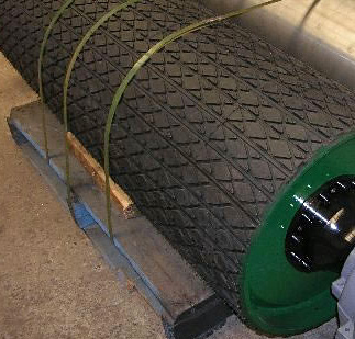
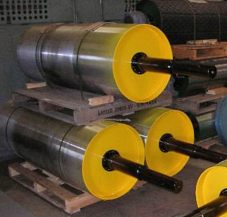
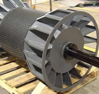
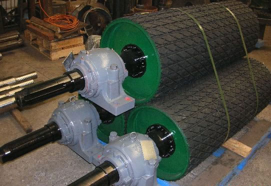
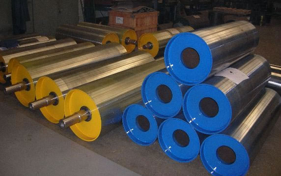
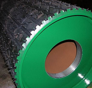
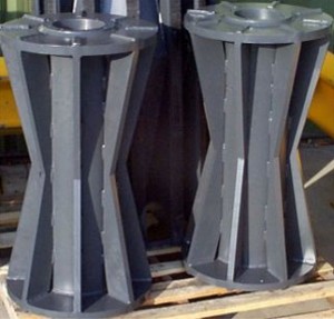
Although the drum pulley rules the conveyor industry with an iron fist, we need to go beyond the above definition to realize the talents of the device. A drum pulley is more than a shaft and an outer shell supported by two circular end plates. For example, the cladding of the shell can be altered to enhance the standard cylinder profile of the product. A crown can be incorporated within the design to aid in belt tracking. Lagging choices in the drum aid in the contact formula that prevents slippage between the belt and the drum. Bearing housings decrease friction events and eliminate vibration. The vibration reduction property is particularly relevant when the conveyor is commuting small components that are not meant to move.

An assemblage of pulley components is initially perceived as a basic convergence of parts, but this judgment represents a misconception, especially when we give credit to the versatility and importance of the part within the conveyor mechanism. Like an integral gear within a timepiece, drum pulleys are built to precise standards. They’re also manufactured to perform in vastly different environments, in mines and quarries, food production lines and pharmaceutical factories. Those bearing housings have to be sealed in a lubricant bath to deliver smooth motion while keeping dust and particulate matter segregated. The drum and lagging operate on the same high performance principle, distributing heavy, raw loads and finite weights with equal determination.

Introduction to Conveyor Pulleys

bearing-setAs long as a conveyor system performs as it’s meant to, it goes unnoticed, which is a tad ironic considering the importance of this equipment within a business venture’s production chain. It’s only when the mechanism stutters to a halt that we give the apparatus the credit it deserves. In the industrial realms where quarried rocks and ore-rich aggregate are conveyed along steel-laced conveyor belts, the parts list we’re proposing rises exponentially, positioning high horsepower electrical motors next to precisely engineered pulleys. Belt cleaners and conveyor guards act as supplementary components while load chutes and discharge buckets sit at either end of this kilometres long belt system, keeping the chain of movement flowing from ore seam to surface processing stations.

Pulleys and Conveyor Belts as Mounted in Industrial Settings
bearing-set2It’s hard to discriminate between these parts when they’re sitting in a sub-surface mine because they’re masked by toughened conveyor belts and narrow subterranean chambers, but bystanders can easily see the importance of pulleys if they stop and look closely. The pulleys appear round when viewed at their profile edges, but the shape resolves to a long cylinder passing beneath the conveyor belt if more light is added to the scene. The rolled cylinders support the belt, lifting and moving the strip horizontally forward or through angled inclines. Further pulleys are strategically located at set intervals along the strip of moving material, acting as deflecting and belt tracking managers until the belt reaches the return pulley, at which point rollers and tensioning mechanisms keep the system tuned. It’s this configuration of pulleys and belts that determine the carriage characteristics of transported raw material.

Placing an Engineering Spotlight on the Pulley
Responsible for both motive force and belt dynamics, the shaft of the pulley is attached to a drive system and freed of friction by lubricated gears and bearings. The rounded profile of the pulley extends outward, covering the width of the conveyor belt as determined by the matter being transported down the belt. The movement of the belt relies on these lubricated parts and the machine fabrication technology used to manufacture the outer shell of the pulley.

Let’s take a break from conveyor system interactions and focus on the drive pulley, a component that locks shaft-to shaft with gears and external motors. Alternatively, there are compact drive pulleys that internalize this configuration, placing the transmission drive inside the cylindrical shell of the pulley. Shaft radial movement, bearing integrity, and a slew of other design characteristics determine the quality of the drive shaft, although the direct interaction between the belt and the shell suggests that the precision manufacturing process used to form the outline of the shell is the determining factor that delineates conveyor dynamics.